Free Shipping on all U.S. orders of $19.99 and more.
Saw Stop
Rail Profile
Recess for the rod
Recess for the rod

Rail details.
Go to our FREE drawing downloads for a better view.
Recess for the rod
Recess for the rod
Recess for the rod
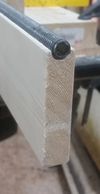
Route 1/2" round, 1/4" deep channel in pine stock.
Secure the rod
Recess for the rod
Rip the rail to width

Cut/Grind/File, flat on end of rod. Then drill hole for screw. A 2" drywall screw was used here. The flat area is not explicitly needed, but it does make it easier to drill the hole if a flat is in place. Secure the rod at both ends.
Rip the rail to width
Optional: Secure Aluminum Strip
Rip the rail to width
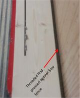
Rip the rail to width, with the threaded rod in place, to provide the most consistent rail width.
Optional: Secure Aluminum Strip
Optional: Secure Aluminum Strip
Optional: Secure Aluminum Strip
Optionally: Drill and counter sink holes spaced 9" apart in 1/8" x 3/4" aluminum strip. Secure to rail with #4 x 3/4" screws.
Completed Rail
Optional: Secure Aluminum Strip
Optional: Secure Aluminum Strip
Rail is complete and mounted.
Carriage details
Prototype Bearing arrangement
Carriage details

Motor and bearings are mounted to a simple flat plate. The motor is mounted stationary, while the bearings are adjustable perpendicular to the rail.
Go to our FREE drawing downloads for a better view.
Carriage details
Prototype Bearing arrangement
Carriage details

The bearing to the far side of the saw, is adjusted to make the carriage perpendicular to the rail, and then locked in place. The bearing closest to the saw is spring loaded, to ensure consistent pinion to rack engagement.
Go to our FREE drawing downloads for a better view.
Prototype Bearing arrangement
Prototype Bearing arrangement
Sacrifical Stop mounted to Carriage
Visible in the prototype, the closest bearing is locked into place, while the far bearing is floating, and spring loaded.
Sacrifical Stop mounted to Carriage
Sacrifical Stop mounted to Carriage
Sacrifical Stop mounted to Carriage
A sacrificial stop is mounted to Carriage. It can be trimmed, profiled, or replaced as needed.
User Interface:
Sacrifical Stop mounted to Carriage
DIY Kit Coming Soon!

User Interface: An Arduino connects to LCD shield for user feedback, PS/2 Keyboard for user input, and outputs to Stepper Motor Driver (with built in power supply)
Go to our Downloads for sample Arduino Code.
DIY Kit Coming Soon!
Sacrifical Stop mounted to Carriage
DIY Kit Coming Soon!
Check back soon for a DIY Kit. With several levels of effort options to choose from. From sourcing all the parts yourself, all the way up to a ready to cut kit, just provide your own rail using the instruction here.
Notes

Accuracy
Initial accuracy tests were promissing for short lengths, but when cutting longer lengths discrepancies large enough to be measured by a tape measure were noted. Approximately 1/16" at 25" and 1/8" at 50". While 1/8" seems like a lot, it is only a 0.25% error. Considering the linearity of the error, it is attributed to the tolerance of the threaded rod, and fortunately was easily accounted for by adjusting the arduino code. Now cuts are produced with no discernible error when compared to a tape measure, and for short lengths results are well within 10 thousands of an inch - well within woodworking expectations.
If building your own system this initial setup test will be required.
Calibration
Calibrating the stop is simple.
- Position the stop and make a short cut.
- Measure the resulting length as accurate as possible (using calipers is recommended).
- Enter the resulting length as the position of the current location.
Interface
Using an arduino allows for near infinite customization of the user interface. Currently the following modes are implemented:
- Absolute location
- Increment location
- Set Absolute location
Homing
Homing of the stop is not currently implemented, but is a relatively easy upgrade. For the time being, the stop is positioned to the zero location before shutdown. When turned back on, the interface defaults back to the zero location so no calibration is needed. If we don't remember to park the stop before shutdown, we simply re-calibrate at next use.
Stop strength/feedback
Since this is a stepper-motor-based system, and there is no positional feedback, care must be used when pushing stock to the stop. If stock is pushed into the stop with too much force, the motor torque will be overcome, and the stop will move, loosing position. In practice it takes some testing to get a feel for how much force is too much, but once that's understood, it becomes second nature to slide stock close to the stop quickly, and then gently push the stock the rest of the way to touch the stop.