Free Shipping on all U.S. orders of $19.99 and more.

Background
CNC machines, or motion control hardware, in general use one of two types of motion drive:
- First is screw type, where a screw and nut combination rotating relative to one another translate into linear motion.
- The second type is a rack & pinion, where a pinion and rack combination rotating relative to one another translate into linear motion, this can take the form of a solid rack, or a toothed belt.
Each type has it’s benefits, screw type arrangements inherently have more torque and high resolution, while rack types are capable of greater speeds. However with developments in driving electronics, these generalizations are becoming more and more blurred.
In the search for a lower cost gear rack system, it was noted that a threaded rod closely resembles a gear rack, and it was conceivable to generate a pinion to mate on this threaded rod. Very similar in appearance to a worm gear drive, except much different in function. This is the basis for the "rod as rack" name. A threaded rod is used in place of a standard gear rack.
Additionally, with this arrangement it is possible to conceive a system that combines a screw system and rack & pinion system. Consider a drive system utilizing two motors, one to drive the pinion, and one to drive the screw. Its possible to have your cake and eat it too!
Frequently Asked Questions
Why aluminum for the pinion?
-Aluminum was chosen for two reasons.
- First, in general more project cost (both material and time) is tied to the rack, as such the intent was to minimize any wearing of the rack, by using a softer material. When the system becomes worn beyond an acceptable point, it is cheaper to replace the pinion. Please note: this does not mean that the pinion will need replaced regularly. Several systems in place have literally traversed the equivalent of many miles, and still show much life to be had, even after several crashes that caused the pinion to skip teeth.
- Second, we specially designed a machine and tooling to make these pinions, and frankly it's easier on the tooling to work with aluminum. As such our tooling costs are lower and we are able to bring you the pinions at a lower cost.
- Note: Very conservative estimates on the strength of theses pinions show 150lbs of axial rod force is possible. Check back soon for a real world demonstration.
Can I make my own pinion?
-Of course you can, it is possible to make a pinion using a rotating threading tap that is fed into a free to spinning blank (often done on a lathe). In fact, this is how some of our first prototypes were made. But here are some of the things we learned:
- It's hard to get repeatable results. Blanks of the same diameter could be produced with different numbers of teeth, and occasionally the process would miss-track producing very ill shaped teeth.
- Often the resulting pinion would suffer from what we term "cogging action". As the pinion would rotate on the rack, you can feel points where it would tend to rest, and other points where the pinion would tend to push away from the rack.
Our pinions are cut on a specially designed CNC machine specifically to minimize any cogging action, and provide the smoothest running pinion possible. We believe we have worked through the headaches and provide these pinions at a low enough cost to make them worth your investment. This way you can spend your time working on other aspects of your project.
How accurate is the system?
-We make no unrealistic promises. This system is simply not capable of tolerances in the tenths (.0001). In fact very few systems are, even if they claim otherwise. Can you theoretically build a system with a resolution of .0001? Yes, but that's far different from actually repeatably positioning at that resolution. With this system innumerable factors contribute, but repeatably within .005" is easily attainable, and .002" or better is possible. We get it, everyone wants to position as accurate as possible, but it comes down to what is actually needed. Good design principles often negate the need for tight tolerances.
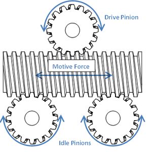
Pinched Configraution
In this configuration, the rod only provides motive force. The system relies on other means for guiding/lateral support. The top pinion is the drive pinion, and is attached to the motor. The bottom two pinions are free rotating, and serve to ensure proper tooth engagement of the drive pinion.
See the CNC router as an example of this configuration.
This configuration also allows for rotation of the threaded rod as a lead screw, providing for a dual driving configuration.
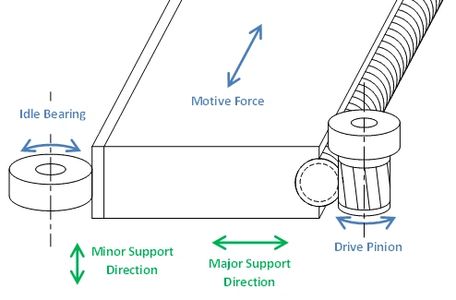
Combined Configuration
In this configuration, the rod provides motive force as well as, in-part, guiding/lateral support. The rod is attached directly to a more robust support. The major support direction is perpendicular to the axis of pinion rotation. Some limited support is also provided in the pinion's axial direction.
Strength: The strength of our aluminum pinion is conservatively estimated to withstand 150-lbs of tangential load.
Engagement: For best results it is encouraged to implement a system of ensuring tooth engagement. Either adjustability which is set and maintained through the life of the system, or preferably a spring loaded system. A spring loaded system has the added benefit of controlling the "slip point" of the system. With a correct pinion pressure one can allow the system to jump engagement during unexpected events, such as contact with end stops, or with work pieces. This helps limit overall system damage. Our pinions can tolerate occasional tooth jump, but it is recommended to minimize this for longest pinion life.
Axial Support: Since our pinions are cut to match the contour of the threaded rod, some support can be achieved in the axial direction of the pinion. Such support is demonstrated in the saw stop example - no additional support is needed to prevent the saw stop carriage from riding up and off the track in normal operation.
Number of teeth and resolution: The positioning resolution is determined on a number of inputs. Our recommended standard rod is 1/2"-10 ACME, which has 10 teeth per inch, and our standard pinion has 15 teeth. Combine this with a half stepping driver and 200 step per rotation motor and each half step will move: 15 teeth ÷ 10 tpi ÷ 400 half-steps = 0.00375" per half-step. Most drivers are capable of dividing each step even further, to the point where any realistically attainable resolution is possible
