Free Shipping on all U.S. orders of $19.99 and more.
CNC Router

Background
This router was built with a purpose, but has proven to be quite the workhorse considering its less than ideal design. It has taken on many forms over the years, and represents a hodgepodge of "just-get-it-done" modifications.
Regardless there's some unique elements, and the overall cost for this 12 foot behemoth was low. It has paid for itself many times over, and shows no signs of stopping.
This was the first test and implementation of using threaded rod as gear rack.

The Concept
The original need, was to build a machine to automate the construction of porch railings. As such it was designed to process long and skinny materials (such as a 10ft 2x4) primarily by making mortise and tenons.
A cantilevered design was chosen for ease of loading materials. In hindsight this luxury wasn't worth the loss of rigidity, since in normal workflow, the carriage is parked at the far end of the machine at program completion.
Now the machine is used for all sorts of projects, structural, functional, and decorative.

The X-axis rail consist of a large LVL beam, with 5/8" round steel bars and is mounted to the table which is constructed similar to a torsion box. A carriage was constructed from 2x2x1/8" steel tubing and uni-strut.
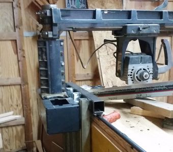
A radial arm saw (RAS) frame was cut down and mounted to the X-axis carriage. The saw itself provided a cheap and quick Z and Y axes and the motor could be easily adapted to hold a cutting bit. Another benefit of the RAS is that the motor could be rotated about two axes, turning the machine into a quasi 5 axis machine.

Drive System
The X-axis and Y-axis were driven by our rod as rack system in a pinched configuration with a timing belt gear reduction and large NEMA 34 motors. In hindsight, the gear reduction and motors of this size, at least on the Y-axis, are overkill. The motors are under driven, and barely get warm. A smaller direct drive motor system would have saved time and money. Due to the mass of the carriage/saw assembly, X-axis accelerations are relatively low, but has not been a noticeable concern in overall function.
The Z-axis was driven by a NEMA 34 motor tied to the original elevation screw of the RAS.
Upgrades
- A 6" extension was constructed for the Y axis.
- The saw motor was replaced with a proper router.
- The original yoke that holds the saw was replaced with a steel version, primarily to support future planned upgrades.